GSM Digital Down Converter in Simulink
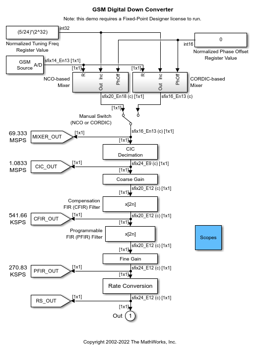
This example shows how to simulate steady-state behavior of a fixed-point digital down converter for GSM (Global System for Mobile) baseband conversions. The example model uses blocks from Simulink® and the DSP System Toolbox™ to emulate the operation of the TI GC4016 Quad Digital Down Converter (DDC).
The DDC performs:
Digital mixing (down conversion) of the input signal
Narrow band low-pass filtering and decimation
Gain adjustment and final resampling of the data stream
In this model, the DDC accepts a high sample-rate (69.333 MSPS) bandpass signal. The DDC produces a low sample-rate (270.83 KSPS) baseband signal, ready for demodulation.
Changing the GSM Source
You can switch between a chirp and a sinusoid signal using the GSM Source block in the example model. You can replace this block with a different source to model your application, however you will have to adjust the parameters of the downstream mixer subsystems.
Adjusting the Normalized Tuning Frequency and Phase Offset Values
To assure that your GSM source signal gets received and mixed down with minimum error, you should adjust the Normalized Tuning Freq Register Value and Normalized Phase Offset Register Value.
Since this example is simulating the TI GC4016 Quad Digital Down Converter, these values must be entered in a particular format. The Normalized Tuning Freq Register Value should be a signed twos-complement 32-bit integer, representing a normalized range between 0 and the sampling frequency. Use positive frequency values for down conversion. The Normalized Phase Offset Register Value should be an unsigned 16-bit integer, also representing a normalized range. For more details, please refer to the TI GC4016 Quad Digital Down Converter documentation and the DSP System Toolbox NCO library block reference documentation.
Comparing the NCO-based and CORDIC-based Mixer Implementations
View the Digital Mixer Real Output scope and Mixer Output Comparison scope to compare the NCO-based Mixer implementation outputs to the CORDIC-based Mixer implementation outputs. Both implementations can be made to produce similar output values, however the implementation choice is based largely on available hardware resources and performance constraints. In general, NCO-based approaches trade off lookup table size (read-only memory resources) with speed performance, whereas CORDIC-based approaches may trade off speed performance for smaller memory resources, based on the number of CORDIC kernel iterations needed.
Adjusting the NCO-based Mixer Parameters
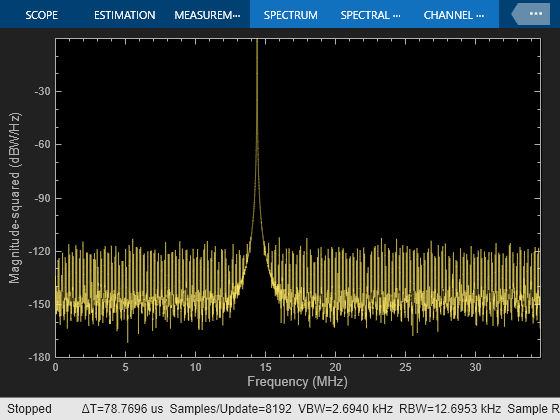
Look at the output of the NCO Cosine Spectrum Analyzer block to observe the effects of tuning NCO-based Mixer subsystem block parameters.
Dithering
To spread the spurious frequencies throughout the available bandwidth, you can add a dither signal to the accumulator phase values. In this example, the dither signal is generated by a PN Sequence Generator consisting binary shift registers and exclusive-or gates (internal to the NCO block). The number of dither bits is automatically determined by
number of dither bits = accumulator word length - table address word length
When you increase the number of dither bits beyond the optimal value, the noise floor begins to rise. When you decrease the number of dither bits below the optimal value, the appearance of spurious frequencies will decrease the spurious free dynamic range of the NCO system.
For more information, please see the DSP System Toolbox NCO library block reference documentation.
Adjusting the CORDIC-based Mixer Parameters
Look at the output of the CORDIC Cosine Spectrum Analyzer block to observe the effects of tuning CORDIC-based Mixer subsystem block parameters.
Phase Accumulator with Dither Generator
The Phase Accumulator with Dither Generator subsystem computes the angle Theta input of the CORDIC Complex Rotate function. Look at the output of the CORDIC Cosine Spectrum Analyzer block to observe the effects of tuning the Phase Accumulator with Dither Generator subsystem parameters.
As in the NCO-based Mixer described above, you can add a dither signal to the phase accumulator values to spread the spurious frequencies throughout the available bandwidth. The dither signal is generated by a PN Sequence Generator consisting of binary shift registers and exclusive-or gates (internal to the Phase Accumulator with Dither Generator). The number of dither bits was chosen to be 15 to closely match the cosine spectrum performance of the NCO-based Mixer.
CORDIC Complex Rotate
The CORDIC Complex Rotate computes u * exp(j*theta) using a CORDIC rotation algorithm. Refer to the Fixed-Point Designer™ documentation to learn about the CORDICROTATE function. Also please refer to the references listed below for more information on using CORDIC-based digital mixer approaches.
Adjusting Decimation Filter Parameters
The CIC Decimator, Compensation FIR, and Programmable FIR blocks are used together to achieve:
A high decimation ratio
Aliasing attenuation
Application-specific filtering
You can use Filter Designer to visualize and analyze the filters. Refer to the Signal Processing Toolbox™ documentation to learn about Filter Designer.
Double-clicking on the CIC Decimator block in the example model lets you see the implementation of the filter. To customize the DDC, you can change the CIC filter by editing the CIC Decimation block parameters.
CIC Decimation filters are implemented using integer overflow "wrap" arithmetic to perform the decimation filtering within their cascaded integrator-comb structures. This type of filter is economical for implementation on hardware such as FPGAs and ASICs, because the only arithmetic operation required is summing; no multiplies are required. For more information on CIC filters please refer to the references below.
The Compensation FIR block adjusts for roll-off of the CIC passband, and the Programmable FIR block filters the signal to meet the requirements of the GSM baseband spectral mask. You can adjust the gain and coefficients of these filters.
The input gain to Compensation FIR filter is set through the COARSE gain parameter. The TI GC4016 Quad Digital Down Converter requires input from a COARSE parameter to shift the output of the CIC filter by 0 - 7 bits, according to 2^COARSE. Thus, you may enter 0 - 7 for the COARSE gain parameter in the Coarse Gain block mask.
The gain at the output of the Programmable FIR block is set through the FINE gain parameter. The TI GC4016 Quad Digital Down Converter requires input from a FINE parameter to shift the signal by 1 - 4 bits, according to FINE/1024. Thus, you may enter 1 to 16383 for the FINE gain parameter in the Fine Gain block mask.
Adjusting Rate Conversion Block Parameters
This final stage of the DDC can be used to change the rate of the output of the DDC to match the baseband frequency of your particular system's demodulator input. The Rate Conversion block is a fixed-point filter that acts similarly to the FIR Rate Conversion block in the DSP System Toolbox. The Rate Conversion block's NDELAY parameter is the interpolation factor, and the NDEC parameter is the decimation factor.
Analyzing the DDC
You can use scopes and the Fixed-Point Tool to observe and analyze the results of your simulation.
Scopes
Double-click on the Scopes block in the example model to gain access to the following scopes:
NCO Cosine Spectrum
CORDIC Cosine Spectrum
Digital Mixer Real Output
Mixer Output Comparison
CIC Decimator Output
Compensation FIR Output
Programmable FIR Output
Resampler Output
Fixed-Point Tool
Invoke the Fixed-Point Tool interface for the example by going to the Analysis menu and selecting Fixed-Point Tool. This interface allows you to see the maximum values, minimum values, and overflows for fixed-point blocks in any subsystem in the example model. Refer to the Simulink and Fixed-Point Designer™ documentation for more information on the Fixed-Point Tool.
References
[1] Hogenauer, E. B., "An Economical Class of Digital Filters for Decimation and Interpolation," IEEE® Transactions on Acoustics, Speech, and Signal Processing, ASSP-29(2):155 - 162, 1981.
[2] Lohning, M., Hentschel, T., and Fettweis, G., "Digital Down Conversion in Software Radio Terminals", Proceedings of the Tenth European Signal Processing Conference (EUSIPCO), 1517 - 1520, 2000.
[3] Valss, J., Sansaloni, T., Perez-Pascual, A., Torres, V., and Almenar, V., "The Use of CORDIC in Software Defined Radios: A Tutorial", IEEE Communications Magazine, 46 - 50, September 2006.
[4] Yang, S., Wu, Z., and Ren, G., "Design and Implementation of FPGA-Based FSK IF Digital Receiver", 1st International Symposium on Systems and Control in Aerospace and Astronautics (ISSCAA), 819 - 821, January 2006.
[5] Andraka, Ray, "A survey of CORDIC algorithm for FPGA based computers", Proceedings of the 1998 ACM/SIGDA Sixth International Symposium on Field Programmable Gate Arrays, 191 - 200, Feb. 22-24, 1998.
[6] Volder, Jack E., "The CORDIC Trigonometric Computing Technique", IRE Transactions on Electronic Computers, Volume EC-8, 330 - 334, September 1959.
You can also select a web site from the following list:
Americas
- América Latina (Español)
- Canada (English)
- United States (English)
Europe
- Belgium (English)
- Denmark (English)
- Deutschland (Deutsch)
- España (Español)
- Finland (English)
- France (Français)
- Ireland (English)
- Italia (Italiano)
- Luxembourg (English)
- Netherlands (English)
- Norway (English)
- Österreich (Deutsch)
- Portugal (English)
- Sweden (English)
- Switzerland
- United Kingdom (English)